Hose Clamps
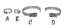 |
All hose clamps are 100% stainless steel for
unbeatable corrosion protection
|
| A: Part # 45734 - 1 1/2" S.S. Clamp, 5 1/4" Long | |
| B: Part # 45731 - 3/4" S.S. Clamp, 3 1/4" Long | |
| C: Part # 45741 - 3" S.S. Clamp, 9 3/4" Long | |
| D: Part # 45710 - 2 1/4" S.S. Clamp, 8 1/4" Long |
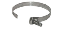 |
Part # 45742 - 3 1/2" S.S. Clamp, 12 1/4" Long |
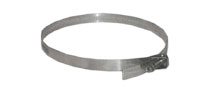 |
Part # 45743 - 7" S.S. Clamp, 22 3/4" Long |
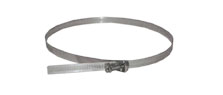 |
Part # 45744 - 10" S.S. Clamp, 32 1/2" Long |
|
|
back to top |
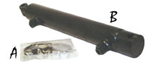 |
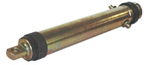
A: Part # 61379 - 1 1/2" Columbus Cylinder Repair Kit |
| B: Part # 45752 - Hydraulic Boom Lift Cylinder | |
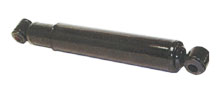 |
Part # 46364 - Shock Absorber for Boom |
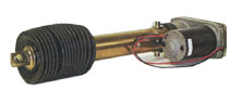 |
Part # 55558 - Actuator w/ Boot Kit |
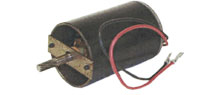 |
Part # 51690 - Electric Motor 12v DC for Electric Lift Actuator |
 |
Part # 51679 - Actuator Kit 8" Stroke |
|
|
back to top |
Foam Markers
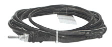 |
Part # 60583 - A-Mark Wiring Harness w/ Switch |
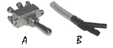 |
A: Part # 55157 - A-Mark Switch |
| B: Part # 55167 - A-Mark Y - 1/4" Y w/ Hose | |
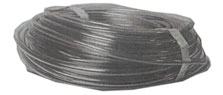 |
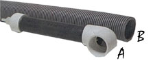
Part # 55743 - A-Mark Hose 1/4" X 100' |
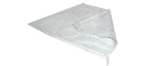 |
Part # 55168 - A-Mark Sock |
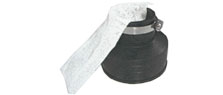 |
Part # 45081 - A-Mark Boot Assembly Includes 1 Boot, 1 Sock, and 1 Clamp |
 |
A: Part # 55166 - A-Mark Foam Chamber |
| B: Part # 55742 - A-Mark Hose 2' |
|
Other A- Mark Part Available:
|
|
|
Part # 54401
|
5 gallon Foam Marker |
|
Part # 54002
|
10 gallon Foam Marker |
|
Part # 59380
|
10 gallon Foam Marker Poly Tank |
|
Part # 55160
|
12v Diaphram Compressor |
|
Part # 55161
|
Liquid Measuring Valve |
|
Part # 55162
|
3-Way Wolenoid Valve |
|
Part # 55163
|
2-Way Solenoid Valve |
|
Part # 55164
|
Intake Filter |
|
Part # 55165
|
Filter Housing |
|
Part # 55241
|
5' Extension Harness |
|
Part # 56981
|
A-Mark Body |
|
Part # 56982
|
A-Mark Needle |
|
Part # 52948
|
15 gallon S.S. Tank |
|
Part # 62582
|
Foam Lip Gasket |
|
Part # 54405
|
Foam Concentrated 1 gallon |
|
Part # 55170
|
Owner's Manual |
|
Part # 61209
|
5 gallon S.S. Tank |
|
Part # 61422
|
Lid Assembly (for S.S. Tanks) |
|
|
back to top |
Charts, Paint, Etc.
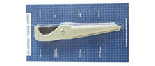 |
Part # 46297 - Lil'
Nipper Hose Cutter Not Shown: Part # 46298 - Replacement Blades |
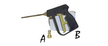 |
A: Part # 45054 - Adjustable Spray Nozzle for Hand Gun |
| B: Part # 47549 - Hand Spray Gun w/ 18" Wand | |
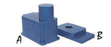 |
A: Part # 46045 - Motor Chassis Cover |
| B: Part # 46044 - Motor Chassis Base (for old style electric oil regulator) | |
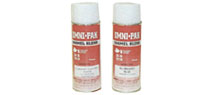 |
A: Part # 46278 - Blue Spray Paint 12 oz. Can |
| B: Part # 65347 - Red Spray Paint 12 oz. Can | |
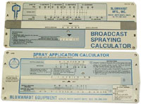 |
Part #'s Top-45761, Broadcast Spraying
Calculator Bottom-45762, Spray Application Calculator |
|
Technical Information:
|
||||||||||||||||||||||||||||||||||||||||||||||||||||||||||||
|
*Not Recommended | |||||||||||||||||||||||||||||||||||||||||||||||||||||||||||
| **Nozzle Height base on 30-45 degree angle of orientation. | ||||||||||||||||||||||||||||||||||||||||||||||||||||||||||||
| ***Wide angle Spray Tip Height is Influenced by Nozzle Orientation. | ||||||||||||||||||||||||||||||||||||||||||||||||||||||||||||
| The critical factor is to achieve a double spray pattern overlap. | ||||||||||||||||||||||||||||||||||||||||||||||||||||||||||||
|
USEFUL FORMULAS
|
MEASURING TRAVEL SPEED
|
|||||||||||||||||||||||||||||||||||||||||||||||||||||||||||
|
GPM = (GPA x mph x W) / 5,940 (per nozzle) GPA = (5,940x GPA per nozzle) / (mph x W) GPM = Gallons Per Minute |
|
|||||||||||||||||||||||||||||||||||||||||||||||||||||||||||
|
NOZZLE SPACING
|
||||||||||||||||||||||||||||||||||||||||||||||||||||||||||||
|
If the Nozzle on you boom is different than those tabulated, multiply the tabulated GPA coverages by one of the following. Where tables are Based on 20" Nozzle Spacing:
Where tables are Based on 30" Nozzle Spacing:
Where tables are Based on 40" Nozzle Spacing:
|
||||||||||||||||||||||||||||||||||||||||||||||||||||||||||||
|
MISCELLANEOUS CONVERSION FACTORS SPRAYING SOLUTIONS OTHER THAN WATER Example: Desired application rate is 20 GPA of 28% N. Determine the correct nozzle size as follows: GPA (solution) x Conversion factor = GPA (from table) 20 GPA (28%) x 1/13 = 22.6 GPA (water) The applicator should choose a nozzled sized that will supply 22.6 GPA of water at the desired pressure.
|
SPRAY ANGLE & COVERAGE Tabulations for spray tips are based on spraying water. Generally, liquids more viscous than water from relatively smaller spray angles, while liquids with surface tensions lower than water will produce wider angles. In situations where the uniformity of spray distribution is important, be careful to operate your spray tips within the proper pressure range. NOTE: Suggested minimum spray heights for broadcast spraying are based upon nozzles spraying water at the rated spray angle. FLOW RATE |
|
|
back to top |